

Parametric 3D Modeling I - OpenSCAD Vase
Welcome to your first lesson in parametric modelling!
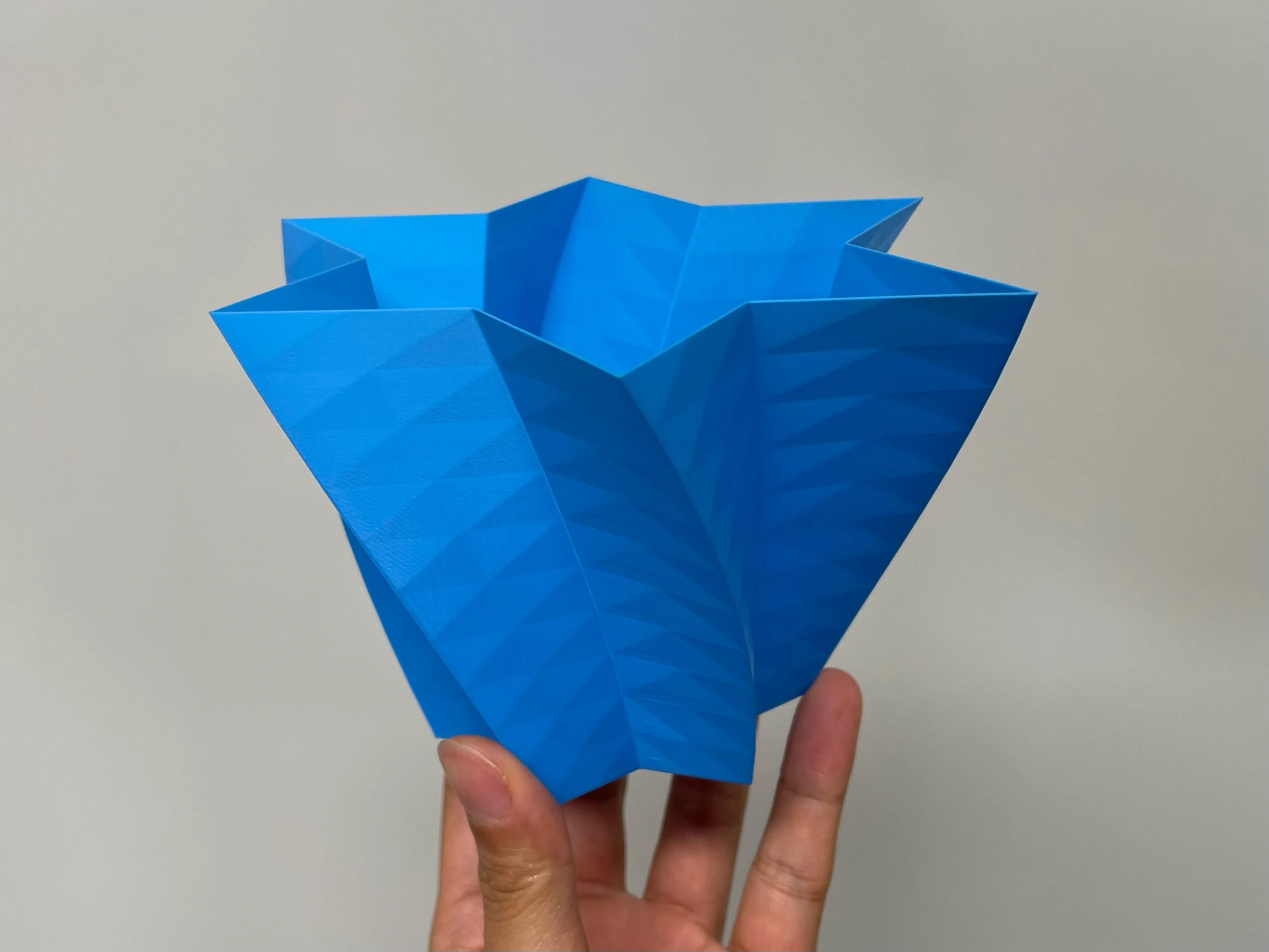
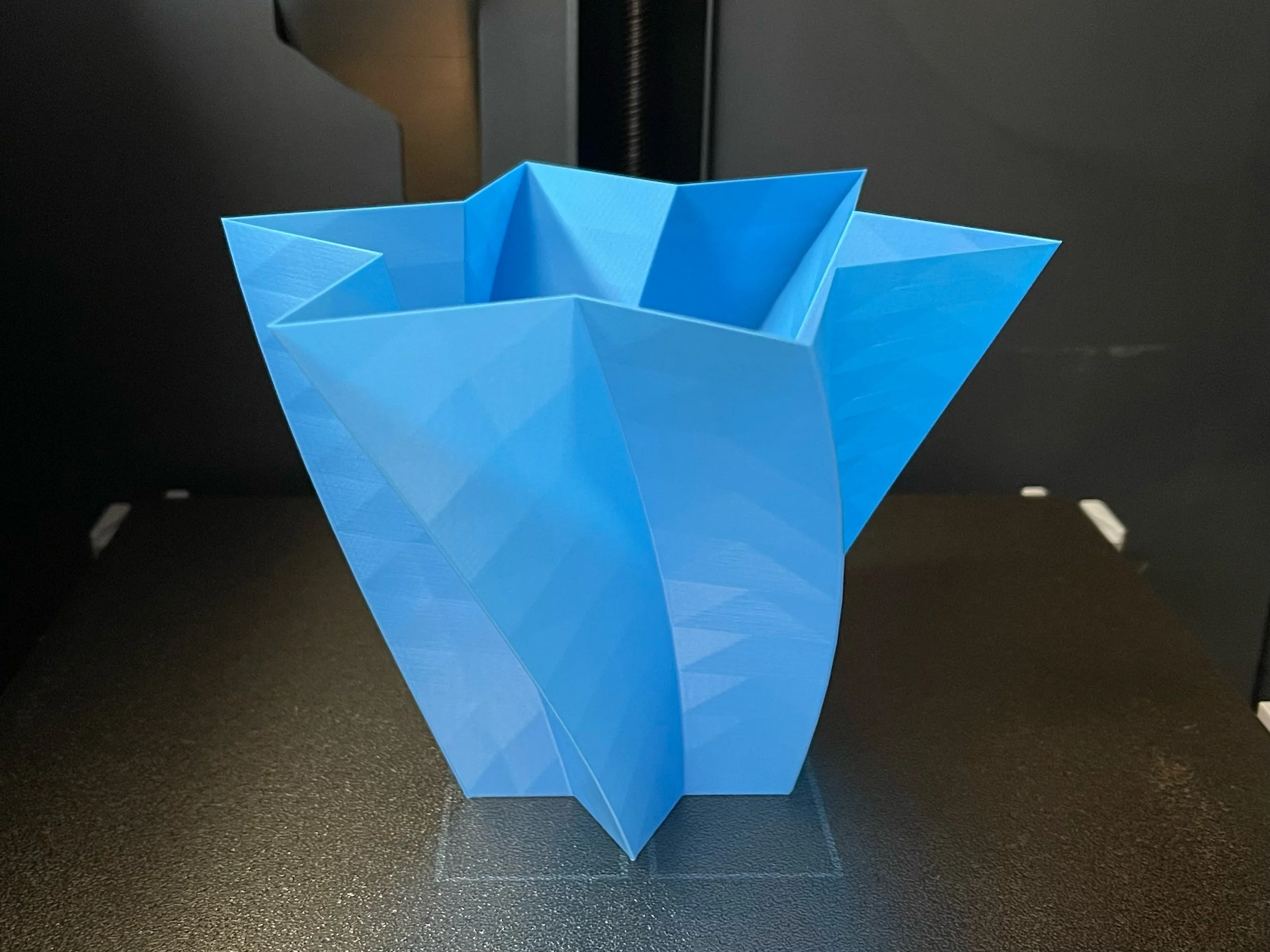
Today we’ll use simple code to design a beautiful 3D vase while practising the Cartesian coordinate system from maths. The vase you designed will be 3D-print, here’s an example of what you’ll have at the end:
Without further ado, let’s get started!
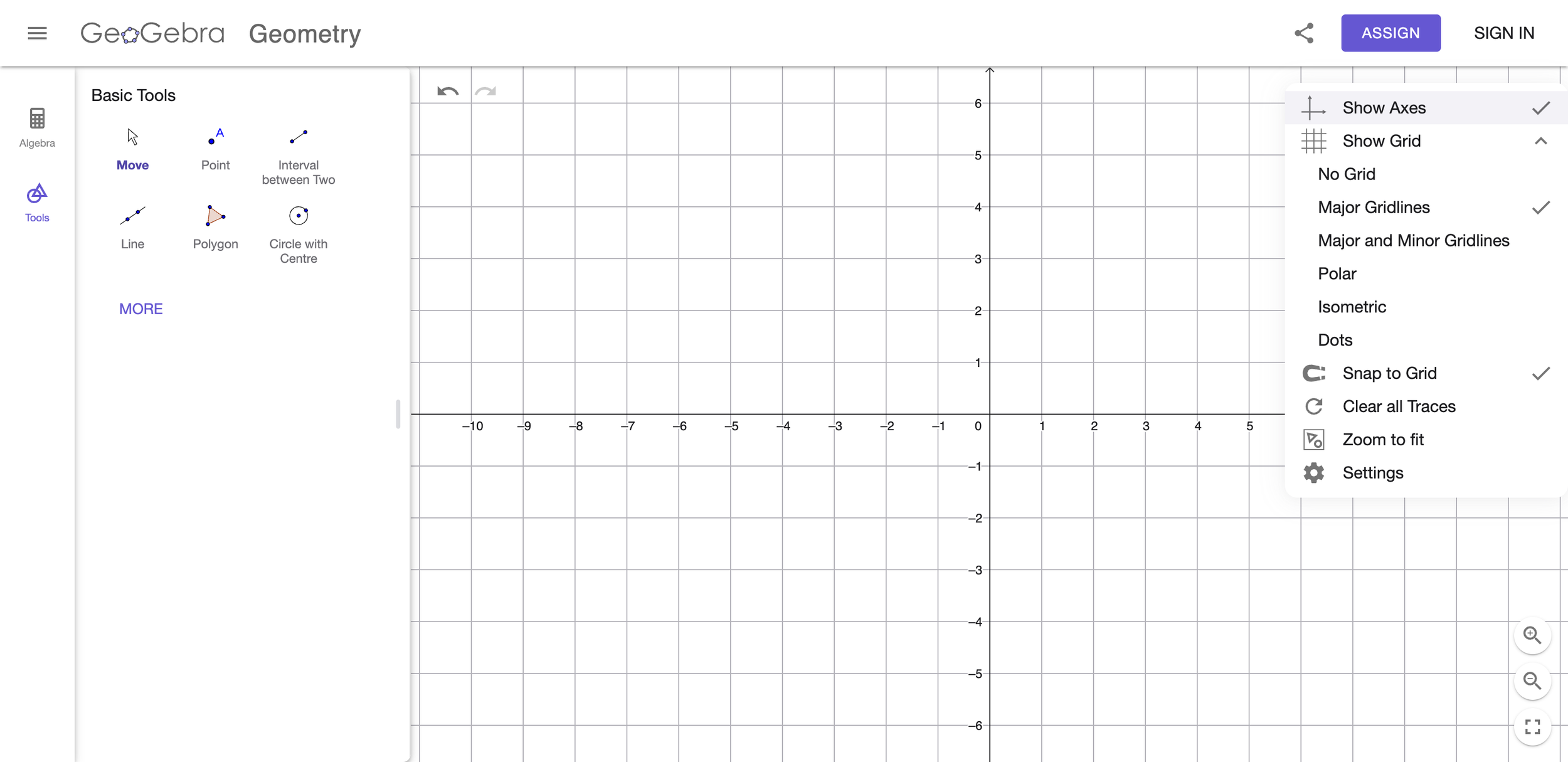
Step 1: Go to https://www.geogebra.org/geometry, click the gear icon (top-right), turn on Show Axes, and under Show Grid enable Major Grid Lines.
Step 2: Use the Polygon tool to draw your base shape on whole-number grid points only; here is a shape I drew that looks beautiful to me—this will be the base outline of your vase, so be creative! To edit, click More and use the editing tools.
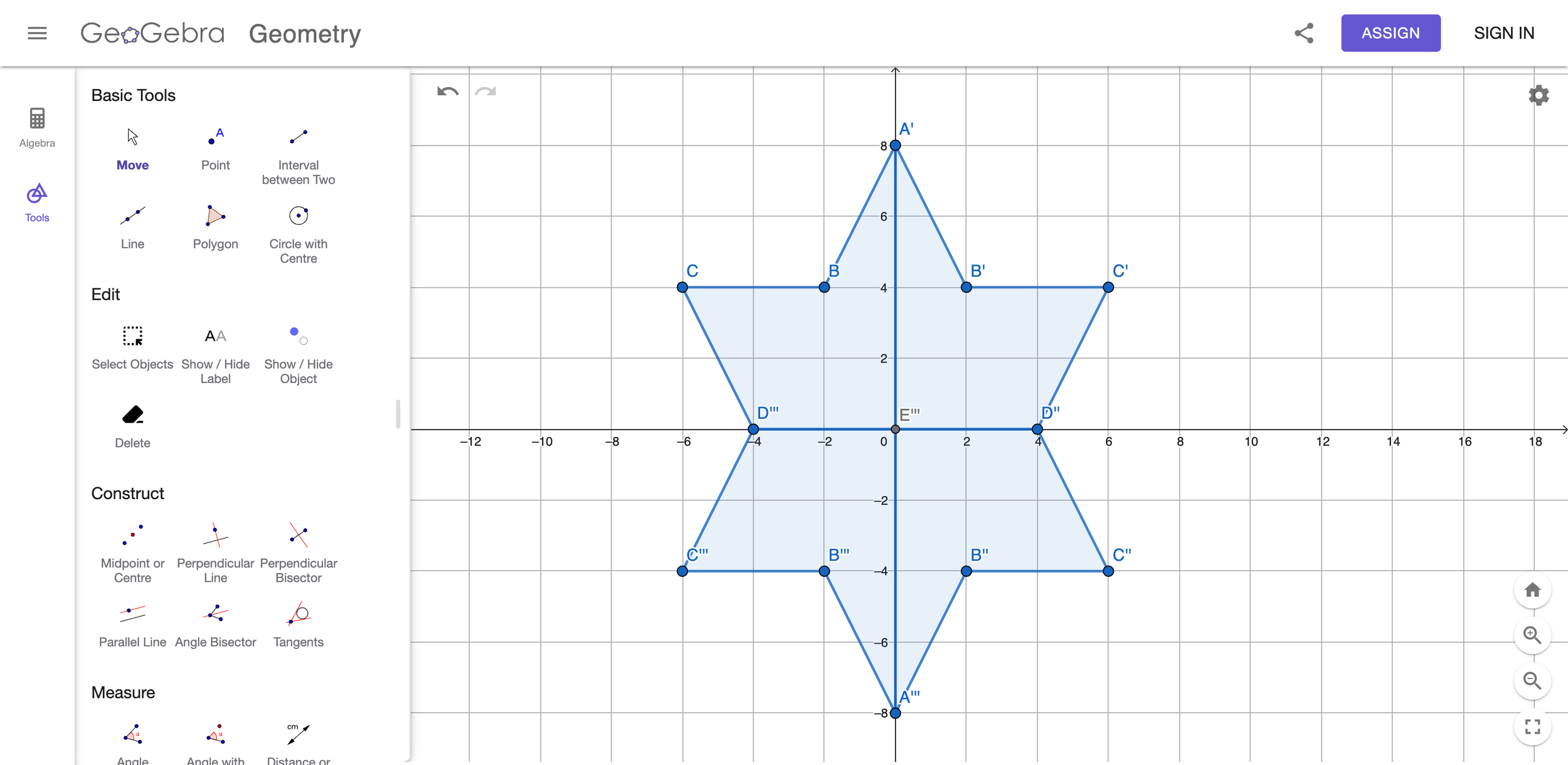
Step 3: Here is the part that tests your knowledge on the coordinate system! Find the coordinates of each vertex of the polygon you just drew (write them in order around the shape, using whole numbers only). For example, my polygon’s vertex coordinates are:
[-40, 0], [-20, 10], [-30, 20], [-20, 20], [-20, 40], [0, 40], [10, 20], [20, 30], [20, 20], [40, 20], [40, 0], [20, -10], [30, -20], [20, -20], [20, -40], [0, -40], [-10, -20], [-20, -30], [-20, -20], [-40, -20].
Step 4: Go to https://openscad.cloud/openscad/, type the code in the image below into the editor. Remember to replace the coordinates with your own polygon’s coordinates (from Step 3)! You can try to change the values of height, twist, slices, and scale to see how your 3D model changes.

Here is the code that you can directly copy and paste into OpenSCAD for your convenience:
linear_extrude(height = 20, twist = 40, slices = 10, scale = 2)
{
    polygon(points = [
        [-4, 0],
        [-6, -4],
        [-2, -4],
        [0, -8],
        [2, -4],
        [6, -4],
        [4, 0],
        [6, 4],
        [2, 4],
        [0, 8],
        [-2, 4],
        [-6, 4],
        [-4, 0],
    ]);
}
Step 5: Congratulations—you’ve just created your first vase with code (your first step into parametric 3D modeling)! Click Export → Export as STL to download your 3D model.

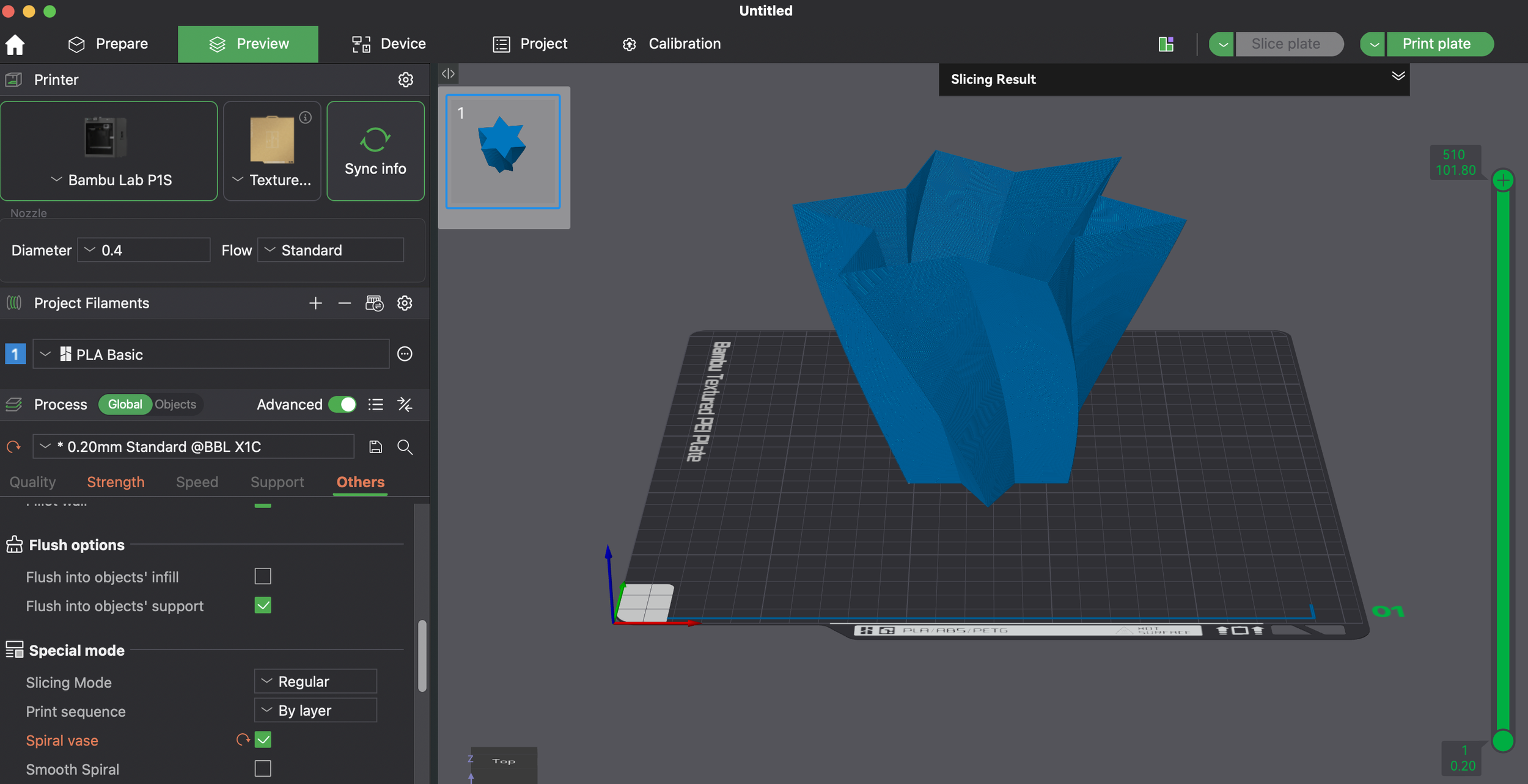
Step 6: In the slicling software, use the “vase mode“ to 3d print the object.
Step 7: Here is your vase 3d printed!
Congratulations! You’ve just completed your first parametric 3D model. 🎉
Hopefully you now have a sense of how this style of modelling works: behind every button and tool are simple rules (code) that control the shape and the operations that build your model—just like the vase you made today.
Next lesson, we’ll explore another core operation: rotate_extrude. You’ll learn how to make a vase with a smooth curved surface using math functions.